You had asked about a system for rinsing filled bottles - coming out of the bottling line.
Add a solenoid to your water feed - that is tied electrically into the water feed solenoid for your vacuum pump.
(or pull the water supply from the output side of the vacuum pump water solenoid)
Locate this system inside the bottling line enclosure - so the water falls on the deck and is directed to the drain.
Use these components to set up a spray system - that focuses under the bottle cap.
As the bottle leave the bottling line enclosure you can dry the bottles with an Air Knife.
Tuesday, May 1, 2012
Tuesday, January 17, 2012
Part Breakdown Drawings.
We finally have drawings for most of the parts on these machines.
This will help immensely in being able to describe and specify spare parts.
Yes, they are in Chinese - but at least we have pictures and numbers!
This will help immensely in being able to describe and specify spare parts.
Yes, they are in Chinese - but at least we have pictures and numbers!

Beer Valve
Inside the bowl - the actuating arm should not rub up and down on the beer valve. The actuator should only touch the beer valve in both the up and the down position.

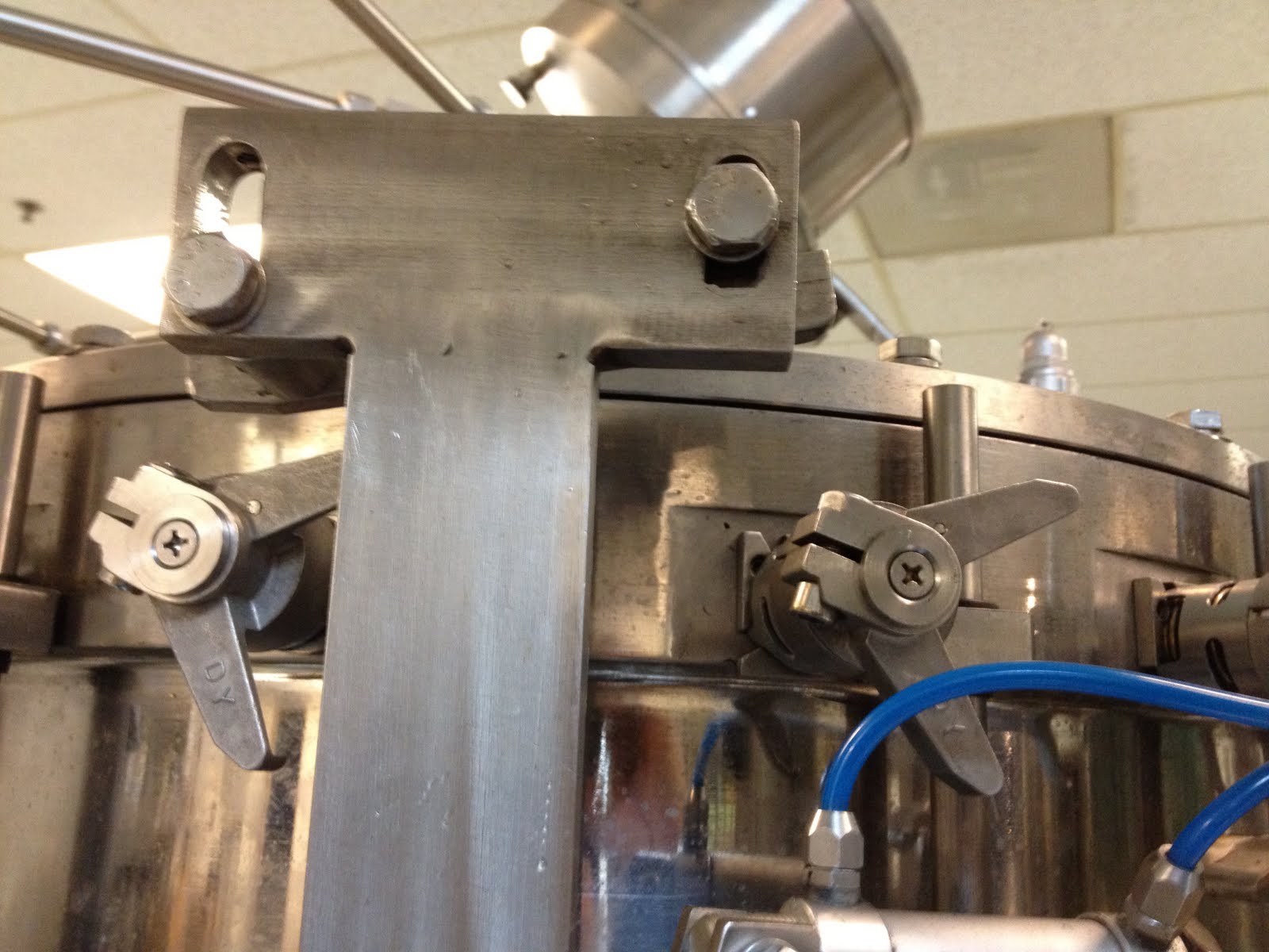
The left hole beer shut-off actuator was modified to be sure that the beer valve was shut off completely.

This operation was performed with a die grinder and carbide grinding burr.

The left hole beer shut-off actuator was modified to be sure that the beer valve was shut off completely.

This operation was performed with a die grinder and carbide grinding burr.
Rinser - crushed roller wheels
I had the pleasure of working - this week - with a technician from the factory in China.
One of the first things that he did was disassemble the rinser heads - and modify the actuating arm that the small roller operates.

Left arm is unmodified - right arm has a new curve.
He used an angle grinder with a sanding disk to reshape the actuator arm to relieve pressure on the the smaller roller wheel.

New spring were also installed. These are a 1.8mmx15mmx43mm

His tool of choice for removing and installing the springs was a 2" binder clip.
He used the black part as the handle - and hooked the spring with the wire loop.
One of the first things that he did was disassemble the rinser heads - and modify the actuating arm that the small roller operates.

Left arm is unmodified - right arm has a new curve.
He used an angle grinder with a sanding disk to reshape the actuator arm to relieve pressure on the the smaller roller wheel.

New spring were also installed. These are a 1.8mmx15mmx43mm

His tool of choice for removing and installing the springs was a 2" binder clip.
He used the black part as the handle - and hooked the spring with the wire loop.
Bearing Grease
If you find that the bearing grease is leaking out of the bottom of your filler you may need to rethink - cleaning the filler. Too much heat can cause the grease to 'boil' creating pressure inside the column and blowing out the bottom grease seal.

With out lubrication the life expectancy of the bearing is very short.
The tapered roller bearing at the top and bottom of the filler column are 180x120x38 Model 32024.
To change the bearings you will need to:
Remove the beer bowl.
This will expose the thrust bearing Model 51126
Remove the threaded collar.
Remove the bottle lifting mechanism.
Remove the gear from the bottom.
Lift the column from the machine.
The bearing can be removed by:
Reinstalling the threaded collar to the column.
Dropping the column on a wooden block.
While this is apart you may want to drill and tap grease fitting - to make servicing easier.
Reassemble with lots of grease!


Temporary larger washer can be helpful while installing the grease seal.

Again - lots of grease!
Note that the lifter deck has been siliconed to the threaded column.
This keep water/beer from dripping down into the tapered bearings below.

With out lubrication the life expectancy of the bearing is very short.
The tapered roller bearing at the top and bottom of the filler column are 180x120x38 Model 32024.
To change the bearings you will need to:
Remove the beer bowl.
This will expose the thrust bearing Model 51126
Remove the threaded collar.
Remove the bottle lifting mechanism.
Remove the gear from the bottom.
Lift the column from the machine.
The bearing can be removed by:
Reinstalling the threaded collar to the column.
Dropping the column on a wooden block.
While this is apart you may want to drill and tap grease fitting - to make servicing easier.
Reassemble with lots of grease!


Temporary larger washer can be helpful while installing the grease seal.

Again - lots of grease!
Note that the lifter deck has been siliconed to the threaded column.
This keep water/beer from dripping down into the tapered bearings below.
Filler 'up ramp'
These bottling lines sometimes have a hard time starting. Part of the problem is that the 'up ramp' feeding the bottles into the filler is at too steep an angle.
This is a photo of the 'up ramp' marked for cutting.
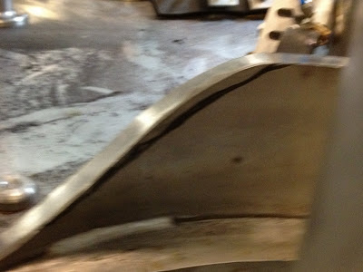
Here is the ramp with the piece that had been cut with a narrow cut off wheel in an angle grinder and smoothed with a sanding disk:

The new 'up ramp' angle:
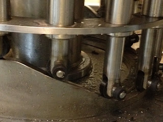
This is a photo of the 'up ramp' marked for cutting.

Here is the ramp with the piece that had been cut with a narrow cut off wheel in an angle grinder and smoothed with a sanding disk:

The new 'up ramp' angle:


Wednesday, November 23, 2011
Spare Parts - work in progress. . .
GWKent will try to maintain a stock of spare parts for this machine.
This list will contain information on parts available from other locations.
The o-ring that holds the black bottle guide in place in the filler.
o-ring dash # -223 - Grainger part # 1RHH6
The tapered roller bearing at the top and bottom of the filler column are 180x120x38 Model 32024.
The thrust bearing Model 51126
Bearing for the transfer star - SFK Ball&roller bearings, part # 61908 2RS
From Motion Industries.
Filler Assembly spread sheet. This document had links to the drawings.
Their are multiple tabs that cover various parts of the machine.
The o-rings and seals in the Fill Valve Assembly drawings.
The back of this catalog has a nice bunch of o-ring drawings - to help you determine the size of the o-ring you need.
This list will contain information on parts available from other locations.
The o-ring that holds the black bottle guide in place in the filler.
o-ring dash # -223 - Grainger part # 1RHH6
The tapered roller bearing at the top and bottom of the filler column are 180x120x38 Model 32024.
The thrust bearing Model 51126
Bearing for the transfer star - SFK Ball&roller bearings, part # 61908 2RS
From Motion Industries.
Filler Assembly spread sheet. This document had links to the drawings.
Their are multiple tabs that cover various parts of the machine.
The o-rings and seals in the Fill Valve Assembly drawings.
The back of this catalog has a nice bunch of o-ring drawings - to help you determine the size of the o-ring you need.
Subscribe to:
Posts (Atom)