About the Beer Bottling Monobloc. . .

Thursday, July 31, 2014

Bowl fill head parts

Below is a list of the gaskets, seals and bearings. The bearing I found is a sealed bearing - and should last longer than an open bearing.
If you want to get the o-rings your self - I would recommend the red food grade silicon material.

I will be ordering these parts in - and the parts are in.

(1) GB10708.3-89 - Dust Ring

(1) QRQR33- OR5334533 O-ring 53.34x5.33

or  2.1 X 0.209 53.34 MM X 5.33 MM o-ring pg 16 of 60  

or Newman #330 pg 8 - 53.34 x 5.33 - pg 8


(1) GB3452.1-85 - 73.5 x 3.55 - 2.874 X 0.137 73 MM X 3.5 MM o-ring pg 20 of 60 
or Newman #233 - 72.62 x 3.53 - pg 7

(1) GB9877.1-88 - seal Ultimate Industrial - UIS50x72x8ADL-NBR-SS

(1) GB3452.1-85 - 4.173 X 0.139 106 MM X 3.55 MM o-ring pg 24 of 60
or Newman #243 - 104.37 x 3.53 - pg 7

(1) GB894.1-86 - snap ring

(2) GB/T278-94 - 61911 sealed ball bearing

(2) QR41A- 3.149 X 0.208 80 MM X 5.3 MM o-ring pg 21-60
or Newman #338 - 78.74 x 5.33 - pg 8

Fill head Drawing

Friday, June 22, 2012

Lubrication, Lubrication, Lubrication!

The Beer Bottling Machine has lots of moving parts - that are trying to work in a pretty hostile environment.
Lots of movement - lots of liquid - some of it sticky - lots of cleaning with chemicals.
It is important that all of these moving parts - be kept well lubricated.
Food Grade Machine Oil or any number of lubricant that are commonly used in the food industry can be used. These lubricants can be applied either with a brush or a spray - but must be applied!

If it moves - it should be lubricated! - to make sure it continues to move smoothly.

Here I have an example of the bottle lifting pistons binding - and 'lifting' the entire lifting ring!

 The first indicator of the problem is that the lifting wheels did not drop down and ride on the rail when in the lowest position.
 Further investigation indicated that the entire lifting ring had raised up from it's original location. The bolt that was holding the lifting ring locked to the shaft - created a gouge in the shaft - on it's way up.

This was caused by a couple of lifting platforms that had started to bind - not moving smoothly - as they were moving up and down. This lifted the entire lifting ring!
To repair this:
- repair all binding lifting pistons.
- loosen the setscrew.
- raise - yes raise - the lifter ring and inch or so - so that the scared shaft can be repaired.
- lower the lifting ring back into place
- retighten the setscrew.
- TIP - add a bead of caulk to keep liquid from running down the center shaft.

Listen to your machine - it 'talks' to you every day!

Tuesday, May 29, 2012

Bottle Rinser

Rinser Adjustments
The whole rinser assembly can be raised up or down to accommodate your bottle height.
The machine should be adjusted high enough to pick up the bottles at the proper height and set them back down smoothly.
Because the bottles can vary in height slightly and not all the rinser heads hang at exactly the same level you may have to have the bottles land a little high to accommodate the variations.

Height Adjustment:
- loosen the bolts on the three legs that support the rinser assembly.
- loosen the two bolts that secure the water line going to the top of the unit.
- under the machine - loosen the jam nut at the base for the threaded rod.
- turn the hand screw to raise or lower the rinser assembly.
- once you are happy with the height retighten the jam nut, leg and water line bolts.

Rotational Alignment:
The (4) bolts over the slotted holes toward the top center of the rinser are for adjusting the rotational alignment of the rinser. 

The two bolt that attach each rinser head to the machine can loosened to optimize the entry of each bottle.

Bottle Jaws:
Before feeding bottles into the machine - as the machine rotates slowly - after it would have picked up a bottle - grab each pair of jaws - and squeeze closed.
If you feel movement:
- check for a weak spring - which may drop the bottle.
- if the spring is good and you still feel movement - you may need to lubricate the jaw arms at the pivot point.
- If the jaws do not open enough to accommodate the bottle neck - check the wheels that open the jaws.
as these ware thin the jaws open less.
- If new plastic jaws have been installed - and the wheel is good - the leading edge of the jaws may need to be ground back to accommodate the bottle neck.


Tuesday, May 1, 2012

Rinsing Filled Bottles

You had asked about a system for rinsing filled bottles - coming out of the bottling line.

Add a solenoid to your water feed - that is tied electrically into the water feed solenoid for your vacuum pump.
(or pull the water supply from the output side of the vacuum pump water solenoid)
Locate this system inside the bottling line enclosure - so the water falls on the deck and is directed to the drain.
Use these components to set up a spray system - that focuses under the bottle cap.
As the bottle leave the bottling line enclosure you can dry the bottles with an Air Knife.

Tuesday, January 17, 2012

Part Breakdown Drawings.

We finally have drawings for most of the parts on these machines.
This will help immensely in being able to describe and specify spare parts.

Yes, they are in Chinese - but at least we have pictures and numbers!

Beer Valve

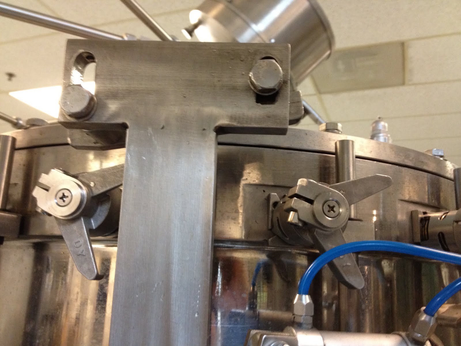
Inside the bowl - the actuating arm should not rub up and down on the beer valve. The actuator should only touch the beer valve in both the up and the down position.


The left hole beer shut-off actuator was modified to be sure that the beer valve was shut off completely.


This operation was performed with a die grinder and carbide grinding burr.

Rinser - crushed roller wheels

I had the pleasure of working - this week - with a technician from the factory in China.

One of the first things that he did was disassemble the rinser heads - and modify the actuating arm that the small roller operates.


Left arm is unmodified - right arm has a new curve.

He used an angle grinder with a sanding disk to reshape the actuator arm to relieve pressure on the the smaller roller wheel.


New spring were also installed. These are a 1.8mmx15mmx43mm


His tool of choice for removing and installing the springs was a 2" binder clip.
He used the black part as the handle - and hooked the spring with the wire loop.

Bearing Grease

If you find that the bearing grease is leaking out of the bottom of your filler you may need to rethink - cleaning the filler. Too much heat can cause the grease to 'boil' creating pressure inside the column and blowing out the bottom grease seal.


With out lubrication the life expectancy of the bearing is very short.

The tapered roller bearing at the top and bottom of the filler column are 180x120x38 Model 32024.

To change the bearings you will need to:
Remove the beer bowl.
This will expose the thrust bearing Model 51126
Remove the threaded collar.
Remove the bottle lifting mechanism.
Remove the gear from the bottom.
Lift the column from the machine.

The bearing can be removed by:
Reinstalling the threaded collar to the column.
Dropping the column on a wooden block.

While this is apart you may want to drill and tap grease fitting - to make servicing easier.

Reassemble with lots of grease!


Temporary larger washer can be helpful while installing the grease seal.

Again - lots of grease!
Note that the lifter deck has been siliconed to the threaded column.
This keep water/beer from dripping down into the tapered bearings below.

Filler 'up ramp'

These bottling lines sometimes have a hard time starting. Part of the problem is that the 'up ramp' feeding the bottles into the filler is at too steep an angle.


This is a photo of the 'up ramp' marked for cutting.


Here is the ramp with the piece that had been cut with a narrow cut off wheel in an angle grinder and smoothed with a sanding disk:


The new 'up ramp' angle:


Once this ramp had been cut the vacuum actuator need to be moved:


Note that the left bracket is now on top of the ring mount. This required that the bracket be narrowed and mounted with (2) 10mm x 75mm bolts.


Wednesday, November 23, 2011

Spare Parts - work in progress. . .

GWKent will try to maintain a stock of spare parts for this machine.
This list will contain information on parts available from other locations.

The o-ring that holds the black bottle guide in place in the filler.
o-ring dash # -223 - Grainger part # 1RHH6

The tapered roller bearing at the top and bottom of the filler column are 180x120x38 Model 32024.
The thrust bearing Model 51126
Bearing for the transfer star - SFK Ball&roller bearings, part # 61908 2RS
From Motion Industries.

Filler Assembly spread sheet.  This document had links to the drawings.
Their are multiple tabs that cover various parts of the machine.

The o-rings and seals in the Fill Valve Assembly drawings.

The back of this catalog has a nice bunch of o-ring drawings - to help you determine the size of the o-ring you need.

Tuesday, July 12, 2011

Beer Level Float

The Beer Level Float can be seen through the site glass in the side of the beer bowl.
When the float, in the beer bowl, is sitting on the bottom - with no beer in the bowl - the input on Siemens S7 processor - I0.0 should be lit.
I have seen cases when the float is at the bottom - and the input I0.0 was not lit.
A smack with a rubber hammer - on top of the bowl will cause the switch to close and the I0.0 light to come on.
We have ordered and received replacement floats to solve this problem.
Contact G.W.Kent at: info@gwkent.com - to order a replacement.

Tuesday, June 21, 2011

Ladder logic for the Siemens S7 processor

Screen shots from the Step 7 software of the ladder logic.

Ladder logic program for the Siemens S7 plc in the beer bottling line 1plc.mwp

To open this file you need to use the Demo version of the Siemens STEP 7-Micro/WIN software which will only work with Windows XP and Windows 2000 (it does not work with Windows 7)

Monday, June 13, 2011

Fill head does not move up and down smoothly

If the the fill heads do not drop down smoothly.

It may be that the guide block is loose.

If the block that guides the fill head moves up and down (see photo) - it can cause the fill head to not drop smoothly.

You can tighten this block by removing the V-handle and tighten the retaing nut.


Wednesday, June 8, 2011

Wiring the Beer In Valve for CIP

The Beer in Valve is controlled by the float valve. Once the float says that the bowl is full the Beer in Valve is closed.

To keep the valve open while running cleaning solution through the machine - you need to keep the Beer in Valve open.

The beer valve is tied to the Siemens processor through o1.0. LinkYou will find o1.0 (or 1.0) down on the terminal strip in the bottom of the control cabinet.

For the switch I used a SPDT switch with (3) terminals. Mounting it in the wire tray cover on the far right (doesn't show up in the picture)

Move the wire coming in from the beer valve at o1.0 - over two places to an empty terminal.

Connect the center terminal of the switch - to the new Beer in Valve terminal.

Connect one of the other switch terminals to the original o1.0 terminal that goes to the processor.

The third switch terminal is connected to the +24VDC supply.

In one position the Beer in Valve would be tied the usual circuitry and be controlled by the float switch.

In the other position the Beer in Valve is 'tied high' causing the beer valve to be open for CIP cleaning.

Wednesday, May 25, 2011

Siemens S7-200 processor - I/O info


This document also includes some of the processor logic.

The above .pdf version is hard to read.

Here is a .dwg file that you can view with Autodesk's True View.

or a .jpg file.

This sites have links to specifications and product manuals etc.

S7-200 processor.

Monday, May 23, 2011

Water in

The Beer Bottling Monobloc requires water in (3) locations.
- Rinser Pump
- FOB Pump

- Vacuum Pump - see - Vacuum Pump - water ring

The Rinser Pumps can be connected to a vessel containing rinse/sanitize water.

The FOB Pump can be connected to a vessel that contains water suitable for FOBing.

These vessel need to provide a flooded input to the pump.

If the Rinsing and or FOB functions will be done with by city water pressure - the pumps can be bypassed.
You can either plumb the water to the pump and disconnect the pumps from the control panel.

Or you can bypass the pumps entirely and plumb directly to the 3/4" id Rinser hose and the 1/2" od stainless steel FOB line.

Water connection & pump photos.

The pump contactor can also be used to operate a water solenoid. The output of the contactor is 230VAC. You will need a solenoid with a 230V coil or a 230V transformer can be connected to the contactor to run either a 120 or 24VAC coil.

Sunday, May 22, 2011

Electrical Diagram for Mitsubishi Processor

Click to go to drawings

1 0f 3 - motors and contactors
2 of 3 - main motor and drive3 0f 3 - processor drawing

Air & CO2 Diagram - filler mechanisms

Air & CO2 Diagram - for the Beer Bottling Monobloc.

Filler mechanisms - photos of the various stages of the beer bottle filler.

Vacuum Pump - water ring

The beer bottling machine uses a  model SK-0.3 Water Ring Vacuum Pump it is a 1.1KW (1.47 hp) motor, producing 0.3 m3/min. (10.59 CFM), at -.096 Mpa (-28.39 inHg). using 15 L/min (3.9 g/min) water.

Photos showing the vacuum pump hook-up. 3/8" water line in, 3/4" id drain hose out, 3/4" id vacuum line (supplied). Needs a 1/2" npt check valve.

Manufactures web site:
web site is available intermittently.

Wednesday, May 18, 2011

Siemens Drive

The two new machines have Siemens Micromaster 420 Drives

Specifics for the 6SE6420-2uc22-2BA1

These sites have links to specifications and product manuals etc.